Tuesday,18-February-2020
Make Xantia`s Clarion radio bit more modern
EN
Maybe like me, you have seen few articles over the internet that explain similar idea what I have done.
Actually, my base intend was to try to crack (somehow) the CD changer input and to add there Bluetooth / AUX function but after few days it come to my mind: why not try to make it over the TAPE place. And as the rest found you can`t just remove the TAPE control. Then, thanks few web forums I follow the guidelines and here below it is the result.
What is little bit different, some suggest, to unsolder the HEAD pins and to use some old empty cassette to stay inside that the player will function.
Well, I cut the audio tracks, and after pushing the small “L-shape” inside with plastic ruler (that on switched ON radio) and it start to work.
So, what I used and how done it:
- bluetooth module and small nice voltage regulator:

As you can see compared to the SIM frame, they are quite small. That 5V regulator can be purchased for about 1.5-2e and the bluetooth 2-5e. Yes, indeed you can use LM7805 as regulator, but that small board do not spread extra heat.
Anyway, between the 9V used for the player and 5V needed for the board, the difference will not be that big so one 1A 7805 and two SMD tantalum capacitor will solve the problem but that small regulator do the job quite well indeed.
- next you open the radio and cut some tracks:


And here was my first mistake. Read carefully and do not repeat it. My guess was that if I cut L/R/Audio Ground tracks and use the +9V and GND pins will work. NO! It didn`t…

There was also errors starting the player side..
So, then I re-connect the audio ground path (A-G) and remove the chassis ground (close to the 9V)
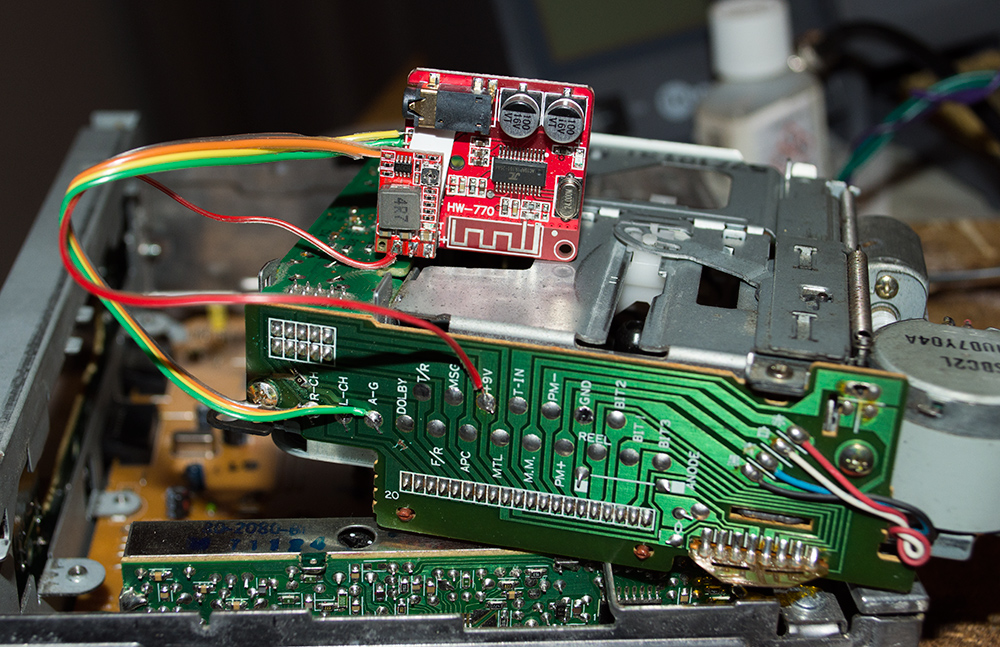
So, now the pins are connected like that:
- 5V regulator fit right on the Bluetooth pad +/- power pin holes
- Bluetooth L/R connected to the TAPE`s L/R pins. Between same BT audio pins is the GND one. It is connected to the A-G pin
- 9V TAPE pin is connected to the 5V board V-IN part.
That`s actually all “magic”. It work quite well. The only “issue” with that Chinese board is the sound that inform you when device is connected or not: it`s some chic trying her bad English..
That done, next what about to replace the old backlight bulbs?


Small 3mm 14V bulbs can be purchased from ebay or aliexpress same as that green “condoms” what cover them. Actually all of them are claimed to be for train models.. but fit perfect for that purpose.
Also, keep in mind that to replace the LCD two bulbs you need to remove the metal bracket. And that bracket also give ground to some of them so test after you resolder it on place.
Then the result is quite good:

And as last word.. In one of the shot you`ll see some small plastic “cap” with two holes. That is the lamp base, so try to nbot lose or break them when you remove the old ones..
Good luck and hope that help you in some way