Tuesday,20-September-2016
Xantia MkII 1999 - Cabin blower problem[fix]
BG: на български език можете да прочетете тук: http://www.clubcitr … 193&start=1002
EN:
There are quite many topics in forums and etc, that give ideas or guides how to fix xantia blower problems. My case unfortunately wasn`t in any of that. Hope my story will be helpful to some of you.
First to clear one thing for the protocol - only if engine is working (alternator signal to the A/C ECU) you can have blower ON.
THE PROBLEM: It was quite rainy day, and suddenly my car`s cabin blower decide to take break. Constant one. There was no life in it on any position even on manual - max speed.
SOLUTION: One female pin in fusebox was loose. As simple as that one can be?

But before that easy part, let me show you what I have done, how I found the problem, and what you can measure before go to the hard part of buying spare parts.
1. electrical diagram. That ones below are only for Mk II model 1999. Seem MkII Xantia 1997-1999 have one design of that, and after 1999 until 2003 have been another one.
2. measurements:
removed the big brown 4 pin plug from the blower. On full ignition,there should be:
- 12 or more volts on red one, and clear ground on thick black one. In my case was 0V on red one(pin 4), and good GND on (pin 2)
- then, next in the list FAN supply relay:
Black test lead, is in it, seen on upper image. There I checked for clear 12 volts on it control pin and good ground.
- Good GND - HAVE!
- Power line from the battery to the blower via BMF1 (40A-engine bay) -> F21(30A cabin) -> relay : HAVE!
- Relay control (+12V) on pin 5, when is on full contact - NO! , there where only 2.3-4.1V
Making small bridge to supply that relay control wire from nearby plug, bring me 12+ volts on my red cable to the blower.
Still, if plug all back - the motor do not move. Next test:
- Pull out that 2 short single wires(black and red) that goes straight to the blower brushes. If give supply from my lighter socket, fan start spinning as fast as possible - so motor is OK!
Next one, based on the electrical sheet - A/C compressor manual activation switch and A/C computer unit. For that, I took out:
- computer:
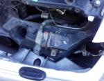
you can find it about hand distance after the cabin filter on vertical. Do not need to take out the glove box. Only one screw driver will help to unlock the pin holding it on place and pull it down.
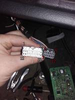
And here how the pin numbers are:
On that electrical sheet, mark 8080 is the ecu. Above it the numbers are for the small plug , bottom - the bigger one.
There, on pin 5(small plug) should come 12+ volts or more to supply the ECU. If the ECU is not properly supplied then it won`t give right signal to the blower control circuit - in my case it was 2.3-4.1V out of 12V!
Next pull out the micro blower - sensor unit, and A/C manual switch

There, I found out that the micro fan is not working at all but the alternator signal(red wire) and ECU signal(yellow wire) are OK. On the A/C button was same story: 2.3-4.1V out of 12V! Same 12+ volts alternator signal was comming ok to the A/C ECU.
If I remove the A/C ECU from it plugs, that make the both other points(relay control and A/C switch) to get proper 12V.
If put it back - again voltage drop on ~2-4V.
All measurements and test until that point are made on working and stop engine. Same ~2-4 volts.
That make me to consider ECU failure, so I bought “new” one from Xsara model 2000.
When fit it and give on contact the result was EXACTLY the same!Engine ON, and.. nothing.
In that moment, decide to check next unit that require power from fuse F12 - motor fan control “BITRON”
My test was: ignition ON, remove the water temp. sensor plug - fan start to run on max speed. All voltage as expected. Same with second (spare unit on my image). Then, measure what come to the F12 output as voltage - good 12 or more volts,and same time only 3-4v on all that points I mention above.
That make me to try - all plugs connected, but with test needle give 12V stable supply from lighter cable to ECU pin5.
In that way, I can hear the HOT/COLD distribution flap to move if I move the COLD-HOT slider. Both engine fans start on low speed. If push the A/C manual switch, then it green led become bright and clear. In same time you can hear the engage sound from the engine bay. And as final result blower start working.
What where the options:
- to find the problem spot
- to fit another supply line
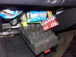
I choose to check first. To eliminate other factors or wire intersections I took the cabin fusebox down:
There where small traces of what moisture can bring on:
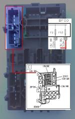
I clean it with contact spray, and focus my attention to the red plug by that diagram:
There should be cable C12M which is the last point for that supply line A/C switch - A/C ECU - blower supply relay control.
And here it is:
If I use multimeter to test:
A/C switch > A/C ecu pin 5 - OK
A/C switch > relay control pin 5 - OK
A/C ECU > relay control pin 5 - OK
A/C ECU > that terminal - OK
A/C switch > that terminal - OK
relay control pin 5 > that terminal - OK
So, there wasn`t any cable broken just that:

It`s clear now, that the connector pin was loose. After tighten it, and also few of the other ones I fit all back and seems it work flawless for now. That was it!
Some thoughts:
How that blower control works, and why the new Chinese models will not work on your semi automatic A/C xantia.
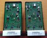
First check that image:
Upper is the original one, bottom is the new unit.
pin 4 - 12-15V supply line from battery. As you can see on old one that goes straight to motor M+ lead, and on new one that line goes via the power transistor
pin 2 - ground, in new module that is straight to the motor M- lead, and on the original it is controlled via the power transistors. Also, is important that in the new one the casting get positive charge!
pin 1 is some kind of line connected to thermistor unit. That unit use the cooler casting as GND. I presume that is connected to some voltage divider in the ECU module. That can`t work on the new module on the same reason as above
pin 3 - ecu control line. If that line give below 1.6V, the SMD elements on the back side of the board can`t switch on, so the relay will engage and the motor will go on max speed. In that new board need voltage to be over 11.8 for the relay to engage.
If the voltage is between 2 - 5 that are the “gears” of the fan speed.
Rising the voltage on the control pin lower the voltage on the brush side pins. That in the original unit. On the new one, what you have on the control pin, same is on the exit.
Again original one - if power supply on pin 3 goes over 12.2 volts on the exit come 0V. The fan stop. So on position “0” on your slider control, on idle engine you should get more than 13V on pin 3.
Can`t remember how it was on Mk1 manual fan control. Perhaps that board will work fine there, or if you “mod” your car - using that board and one 10kOm pot to control it.. but here…no chance


