Friday,16-February-2018
3×74HC595 - arduino simple test
EN
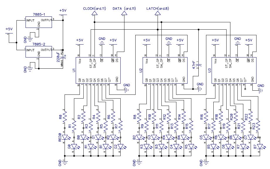
parts: one arduino uno, 3 x 74HC595, 8 x RGB diodes with common ground pin, 8×220ohm resistors for the red pins, and 150ohms for the rest. Power supply: two 7805 regulators in parallel. Seems in that way do not overheat if all LEDs are on full power, 3×220uF caps, and one 47nF cap. 12V as supply.
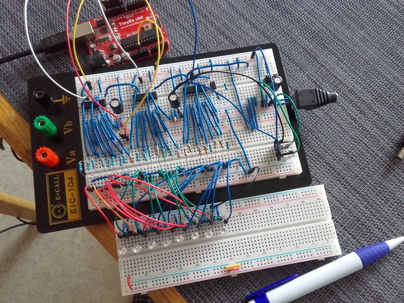
the story: there was again some idea of car dash backlight and that was just test what can be created.
Here is one simple diagram:
and some code:
#define DATA  11  //pin 14 on the 75HC595 DATA

#define LATCH  8  //pin 12 on the 75HC595 LATCH

#define CLOCK 12; //pin 11 on the 75HC595 CLOCK

long demo[] = {

//0  1  2  3  4  5  6  7

//RGBRGBRGBRGBRGBRGBRGBRGB

0b100100100100100100100100,//R

0b010010010010010010010010,//G

0b001001001001001001001001,//B

0b110110110110110110110110,//RG

0b011011011011011011011011,//GB

0b101101101101101101101101,//RB

0b000000000000000000000000 //

};

void setup() {

  pinMode(DATA, OUTPUT);

  pinMode(LATCH, OUTPUT);

  pinMode(CLOCK, OUTPUT);

}

void loop() {

    for(int f=0; f<7; f++){

            digitalWrite(LATCH, LOW);

        for (int c = 0; c < 24; c++) {

            digitalWrite(CLOCK, LOW);

            digitalWrite(DATA, LOW);

             digitalWrite(DATA, bitRead(demo[f], c));

            digitalWrite(CLOCK, HIGH);

        }

    digitalWrite(LATCH, HIGH);

    delay(1000);

   }

} //end loop
Few words: my first led is R0 on the left register, and continue from left to right. Every data is stored in array and that code work exactly as you see. “0b100100100100100100100100” > led 0(bit0), led 1(bit1)…. led 31(bit 31)…
My second try was using left register(N1) as to control all REDs , middle(N2) all GREENs, right(N3) all BLUEs. In that scenario, every shift register OE pin was connected to arduino PWM pin and was able to use “analogWrite” to control color brightness.
It seems to work good, so maybe soon will new “article” in DIY style..