Sunday,21-April-2019
CAMTOOL CNC V3.3 board issues
EN
So… here is the story. I bought myself that very same cnc shield - CAMTOOL CNC V3.3. Owning for some time in the past woodpecker cnc board. That one look new-ish and more sophisticated(big mistake there), and guided from price at one point and the good feedback from the other bought one from A*liExp**s.
When the board come, and found out that not all is butter and honey, pinky or lovely as advertised.
If you happen to drop on that article, please read the follow to know what to expect.
After the package arrived, and fit power supply, add it to the computer (no motor shield or spindle attached) and here it goes:

- spindle led on(so, some extra current flow wrong)
- the board stay connected for about 2-minutes and then disconnect
- that CH340G and Atmel chips get quite hot somehow fast..
So far NOT so good…
First I removed all filter capacitors (red squared marker) and the spindle red resistor. Much handy to add proper one, straight on the motor pins.

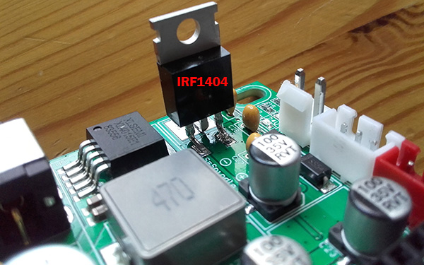
Suspected also that the original mosfet was somehow not behaving well, and decide to replaced with better NPN one.
New one is IRF1404 which can handle up to 60V and 160A..By paper. Really? How exactly you can put 160A via 2mm pin?
Anyway, next in the list: CH340G serial chip

you can see in the corners on that upper picture, example how exactly that should work as simple diagram. First and really noticeable is the resistor added on the quartz oscillator. Exactly same problem is present in the Atmel side, but for that later on.
On the same picture you can see also (second red arrow) that DTR is tight to GND for some reason. You do not need that at all in that set up, so that capacitor and resistor was removed. Only the capacitor removing will do the job but I remove them both.
Next, was removed FU1 - that fuse bridge supply 5v from the computer`s USB port. For right communication, you need RX/TD(USB data line) and GND. Taking 5v power from the board itself only work really well.
After removing the oscillator resistors, the board was prepared for 22pF capacitors that must be added. Here it is:

Here, in the next picture You can see how the capacitors where soldered(blue arrows)

red arrow, show removed capacitor and resistor. The violet one show the moment just before to add resistor between mofset`s GATE pin and ground. In that way you should keep in PWM mode that pin low when must be low.
How it drive the GATE? There is that Q11 optoisolator (right from the orange arrow). It is driven via resistor from the Atmel`s pin. It switch on/off 12V supply to the GATE. There on R16 for some reason was resistor. I replace it with SMD bridge - 0ohms
In that way 12V pass as 12V free.If the plan was to use optoisolator then can be tight even straight to the power supply line.
or power source switched straight to the gate. That mosfet`s gate driven voltage can be as high as 20V. So, my power supply is 20V.. perfect. But do not plan to do some changes there.
That very same 12V line supply R17 and R50. They play role as voltage divider that supply also logic voltage 0-5V for the Laser TTL pin. Good, but not so good. The original was 330 and 220ohm resistors what give something like 0-4.6 volts max and also because of some 1k resistor on R16 position it was even down to 4.45V max. Now with 680 and 470ohms and bridge as R16 it went 4.85-4.9. Maybe is better to use signal straight from the Atmel`s pin but so far it control that optoisolator so too much current will be drawn and we can get into trouble. In that resistor replacement all seems fine for now.
Last thing is on that picture(blue arrow):

All MS1/2/3 , or driver`s micro stepping control pins are tight to HIGH (5v) via some 1k resistor, or 1:16 resolution.
Have no clue why they decide is better than the user too choose 1:1 , 1:2, 1:4, 1:8 or 1:16..
That also can be fixed, but the solder metal is that new type and so hard to remove, so maybe will leave it as it is..
So far, after all that mods, the board work well, even I put the spindle to spin and axis motors to run for more than 5min-10min.
Do not overheat, no disconnecting.. As next step, maybe better to replace that 7805 regulator with some of that new mini boards that actually have reasonable price and almost zero thermal print..
Thank you for reading, and hope it help you in some way..