Monday, 3-June-2019
VW Passat 3B5 : retrofit trip computer and cruise control
EN
In that topic, I will explain what I have done to that Passat 1999 / 1.9TDI. So far to my knowledge same can be done to petrol ones also, but didn`t try it so do not take that manual to be good guide for petrol or any of the new ones as B5.5/B6
What you need for the project:
- car to break
- free time
- and some parts..
Ok, joke aside what must be considered:
!!! BEFORE YOU EVEN START !!! : if you do not have VCDS and access to cable (vag tacho) or other way that you can pull the PIN from the “new” cluster better do not start that procedure!
instrument cluster : both should be the same type. In my case, that what I took to replace the original was from UK model, but for that little bit later.
Both of the clusters must be same type: with or without CAN support. For that car must be without CAN
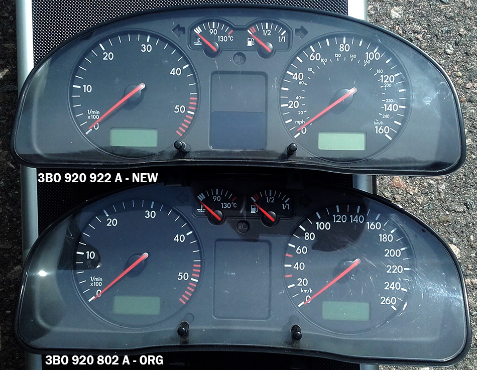
Somewhere, I read that is important the clusters to be from the same base type: like in my case 3B0 920 xxx x
That is based on internet research, so can`t prove or denial it.
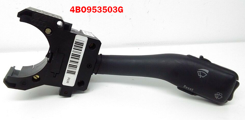
Having new dash with trip / fuel consumption functions, next need wiper control stalk with buttons to control the trip computer: 4B0 95350 3G
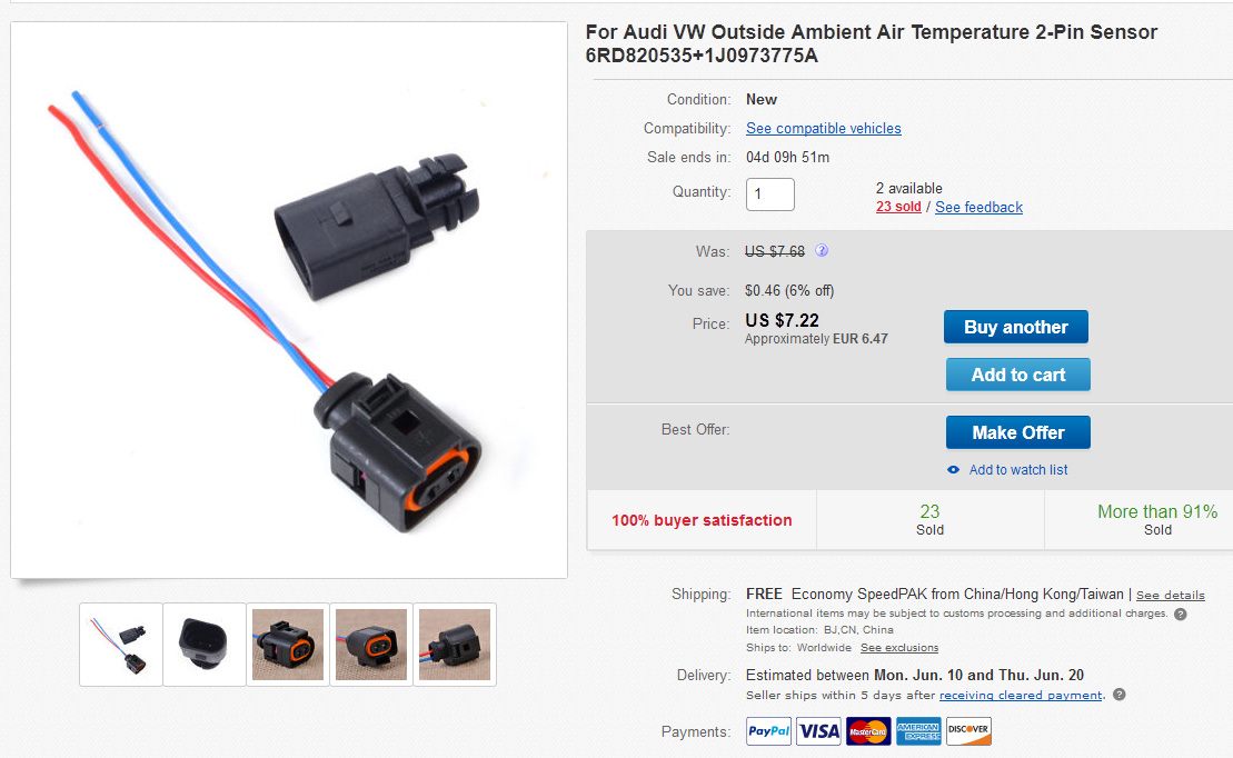
Having the cluster, stalk to control it, next in the list is the temperature sensor: 6RD820 535 / 1J 097 377 5A
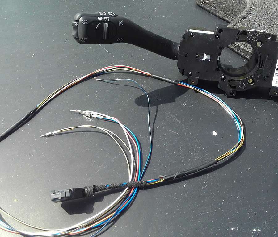
Next in my list was : cruise control
For that one, I bought the cable loom and stalk from Aliexpress.. And honestly, it look good and so far (2 months) still work, but is.. well.. chinese quality. So, my advice is to find original in good shape (maybe from scrap yard) and only buy loom from ebay/aliexpress.
Just to let you know, that loom plug is fine and fit, but the pins(on the other side) that suppose to fit inside the connectors close to the ECU are way too big and there is another challenge but… for that one will speak after while.

Unfortunately you need additional clips pins that will be used to create your car`s missing loom for that trip function.
So, the OEM pin numbers are:
000 979 018 E - small ones, that fit inside the green connector and
000 979 133 E - big ones, that will be used inside the big plug that connect to the stalk.
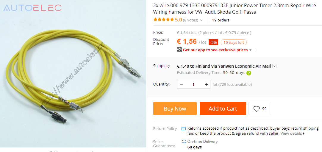
That big ones **133 you can buy either separate:
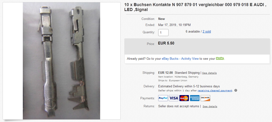
or in ready cable:
The problem is with the small ones: (on the white paper)
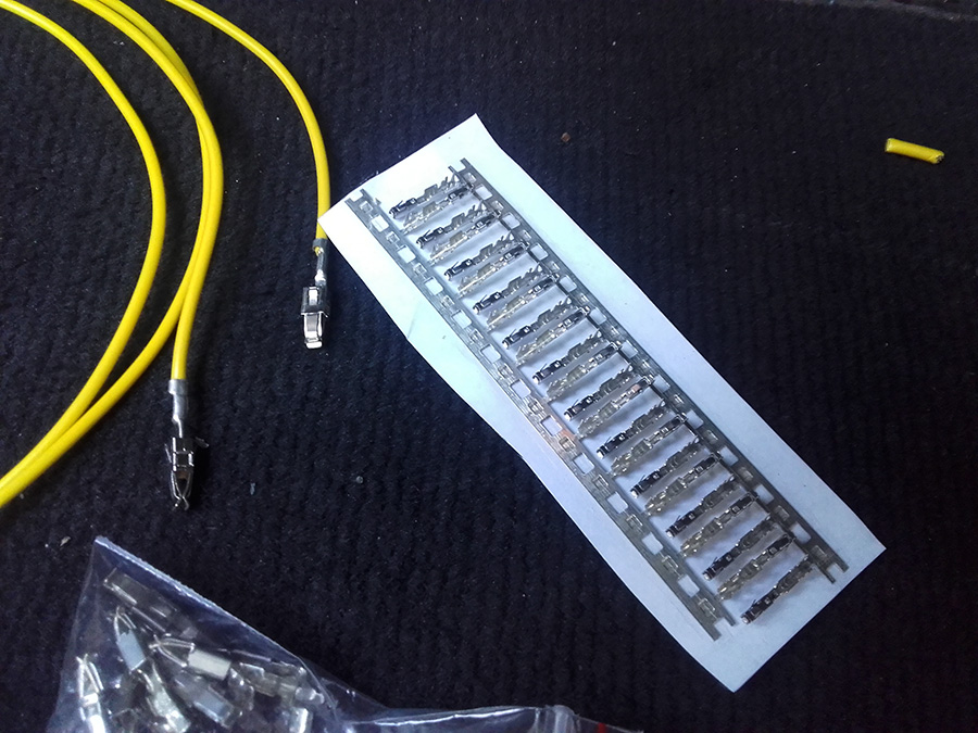
Them, I found somewhere in some EU online shop, and the price was not as for example for Aliexpress 2.54 JNC ones.
Perhaps, you can try again from scrap yard to get that green plug(you`ll see it in a minute) cut together with 15-20cm of the loom, and pull how many pin-cable parts you`ll need.
Now, presume you have all parts need what`s next? > dismantle the cluster.
How? > here it is how to do it:
- remove the negative lead from the battery and wait about 3-5min.
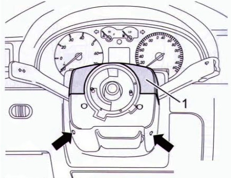
- turn the steering wheel vertically. In that way, you can remove the airbag:
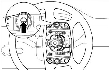
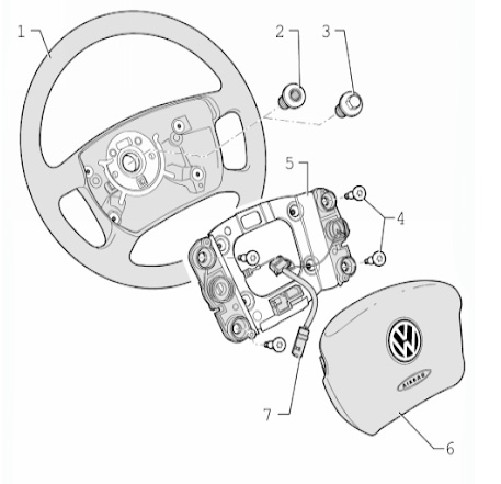
Still don`t get it? No worries, I also was quite annoyed that somehow didn`t happen from the first shot. The reason is that you need to have clear picture what is behind.
The “lock” is kind`a pin which is kept by one spring:
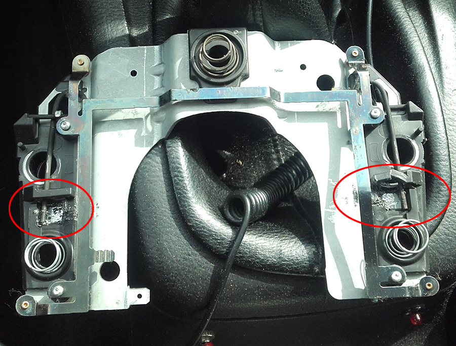
You need not so long flat screw driver, that will “push” that “leg” (you see the scratches) little side way and then the pin will be pushed out by the coil spring.
Be really careful to not pull the airbag and to break it cable`s connector!
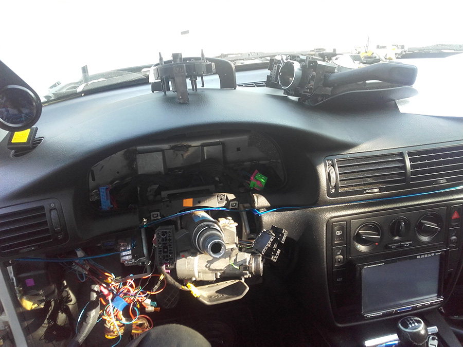
Now, turn the wheel again horizontal , and you come to that state:
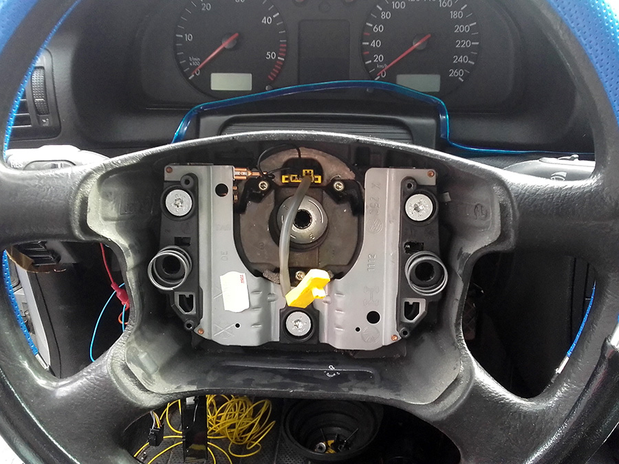
- remove all connectors there, and remove the bolts what keep the chassis
- remove the under cover:
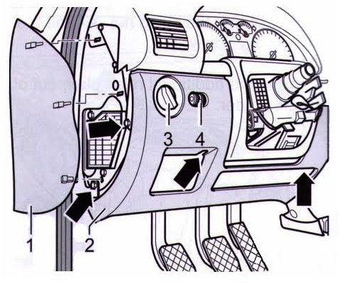
- then the side fuse cover (can be necessary later on)
- now remove the steering wheel. That is one of the complicated parts. It is tight about 80Nm and have thread lock glue on it. I have Milwalkee M18 powerful cordless gun so it crack the bolt in second. But if try with some wrench and sockets keep in mind that will be hard!
Really important !! : mark how the wheel was in place over the column. Use marker or scratch with something sharp.
Now you can proceed:
- steering wheel removed, next are the plastic covers -> first, the top one
as you see, there are two bolts (if remember, it was philips type). After the top is removed, add some strong tape on the coil cable ring to not move and for non reason DO NOT rotate it here and there.
- now you can take out the bottom cover:


- remove the cable coil unit
- loose the screw that keep the stalks on place and unclip all plugs from it
- next in the list, the cover “shield” on back side:
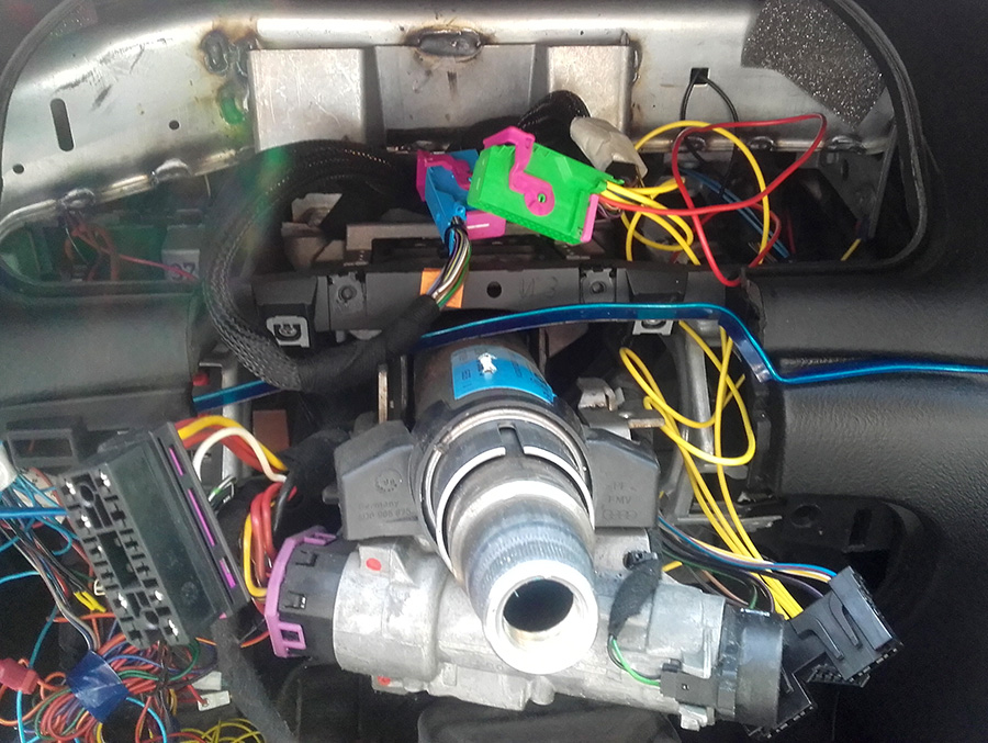
That one removed, you come to some state like that:
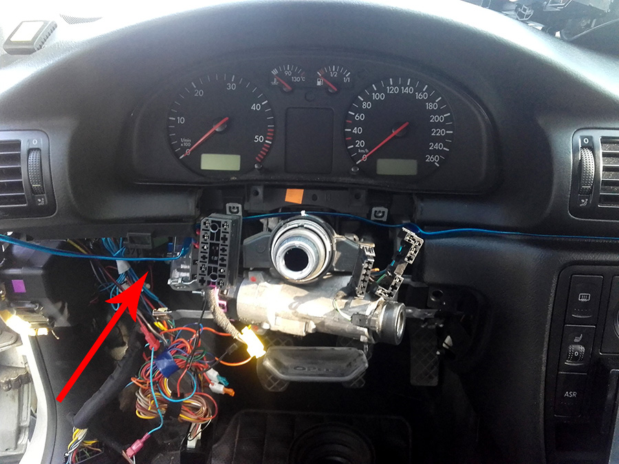
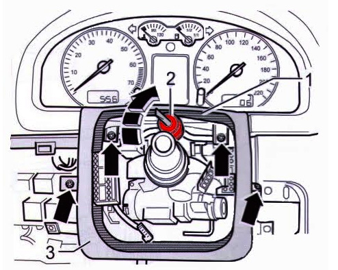
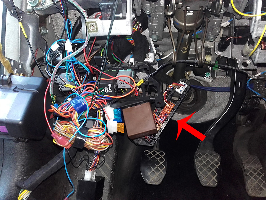
- the two bolts what keep the cluster on place removed, you can pull it out. How?
Well first, you need to put your hand under the cluster (about the red arrow direction) and undo the blue plug.
After that, pull the cluster toward you, and undo the green one.
Congrats, you should see something like that:
Now is the time to do the first loom for the trip slash new cluster:
- cut the black zip tie that keep the cables tight on the green plug
- remove the bottom violet cover
- carefully push with small pin/screw driver from the top side. Then the inner part slide out:
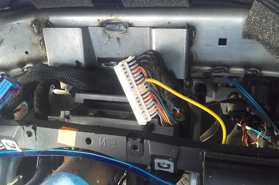
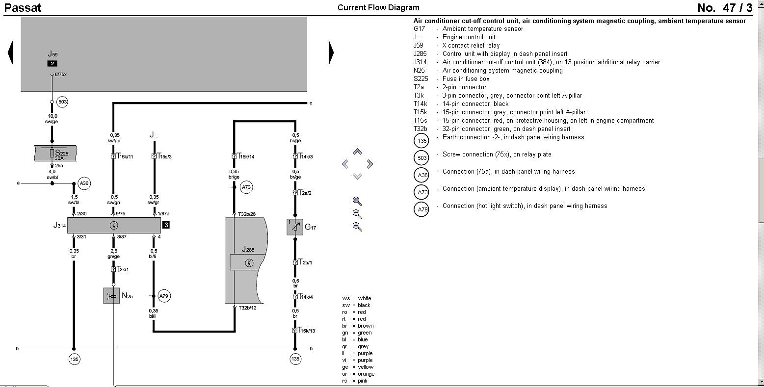
- on the green plug which is T32b (if you look on the wire diagrams) pin positions are marked. So now you need proper length cable that contain both ends the pins what I mention above.
In some websites is quoted 0.75mm2 cable, but trust me 0.5mm2 is perfect! You`ll know when you see..
- the right side the big plug is that we need to open also to start that procedure:
And the cables goes like that:
T32B pin 23 <[small pin] --- [big pin]> stalk plug PIN2
T32B pin 24 <[small pin] --- [big pin]> stalk plug PIN1
T32B pin 25 <[small pin] --- [big pin]> stalk plug PIN4
GROUND(on some bolt) — [big pin]> stalk plug PIN3
T32B pin 26 <[small pin] --- [big pin]> red cable G17 - temperature sensor. On that temperature sensor the second cable (blue) must be on GROUND in suitable place. The sensor itself originally stay behind the front bumper, but you can fit it what ever place you like to be.
As good ground bolt I use one inside the cluster area:
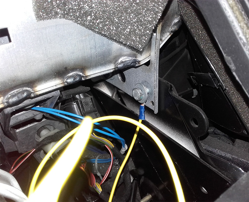
- now let`s say you`re done with the cables and have something like that:
now, you get it why you need smaller size wire? Yep, because the place is so tight inside the plug and that wires are only for signal control and none high amperage will go through..
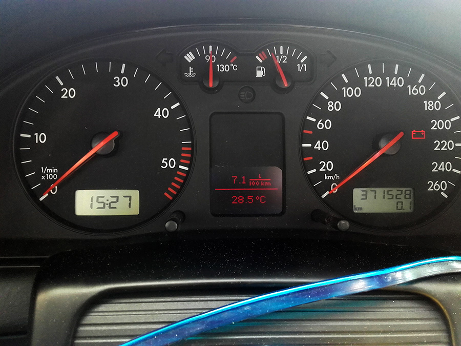
Now, in your case you can just fit the new dash cluster with the trip computer screen. In my case, was that crappy situation. The cluster itself, was from UK model and it was in MILES.
So, I took it apart:
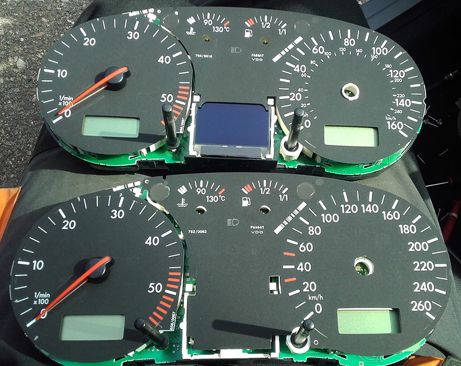
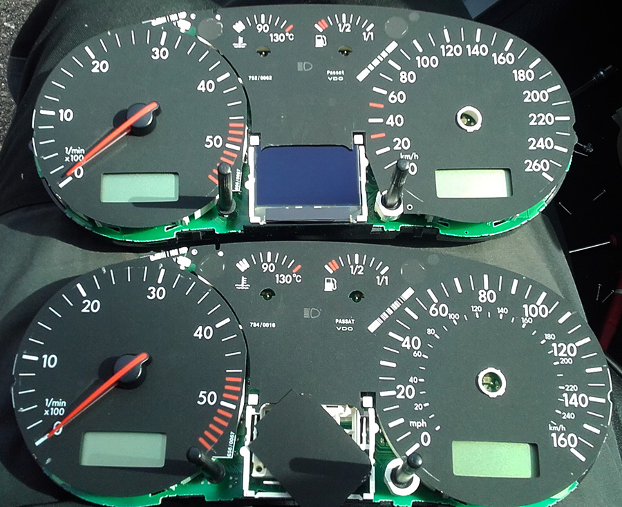
And cut on the old one the same “window”, and use the background plastic with proper EU measurement.
HINT: - with VCDS you can switch it to KM. So, all measurement will be shown in SI units, and also on the small right LCD will change to “km” icon. The problem was only that speedo zone.
HINT 2: if you wish to test the instrument cluster on “bench” at home, you need single JNC 2.54 small female heather cables and the follow connections:
T32B [green plug]
pin 6 - wiper liquid -> GND
pin 7 - break pads -> GND
pin 23, 24, 25 -> stalk -> ground (trip computer control)
T32A [blue]
pin 1 -> +12V (simulate ign key)
pin 19 -> ABS lamp -> GND
pin 22 -> coolant lamp -> GND
pin 23 -> +12V (constant, connected before pin 1)
pin 7 -> GND
pin 9 -> GND
pin 24 -> GND
pin 25 -> K-line (VCDS .. or other diagnostic)
pin 26 + pin 27 -> +12V [backlight]
Now : cruise control
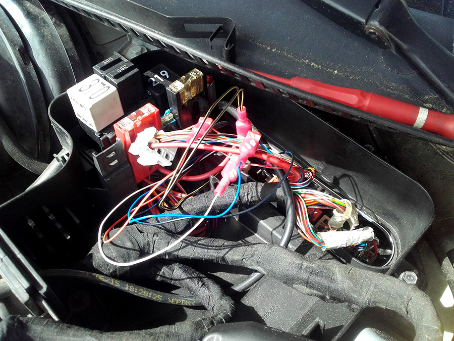
Any tip, or retrofit instructions what you can find will guide you to remove the ECU (yes you need) and then to remove the bracket that keep that few color plugs (close to the ECU) and fit the new extra loom pins there but… will not happen. Why?
Here it is why:
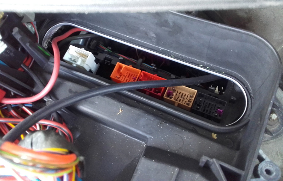
From that view point, there are two blots to be removed (shit..), Then even you remove them.. you need to pull that bracket under all the looms and relay holders (they must be unscrewed too):
And as I said somewhere in the beginning : that loom is made in China, so their pins are really big and not fit!
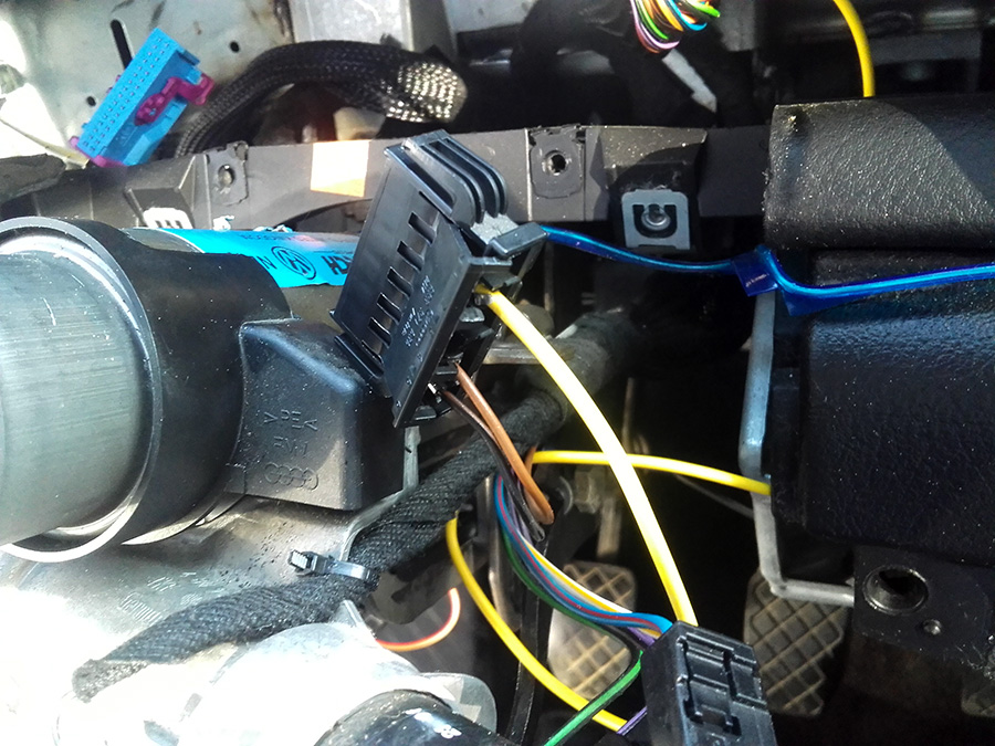
So, before to loose hours and some parts of your finger`s skin use fast clips like that:
Once we know how to connect the cables, need to know : where!
And for that reason here are graphics:
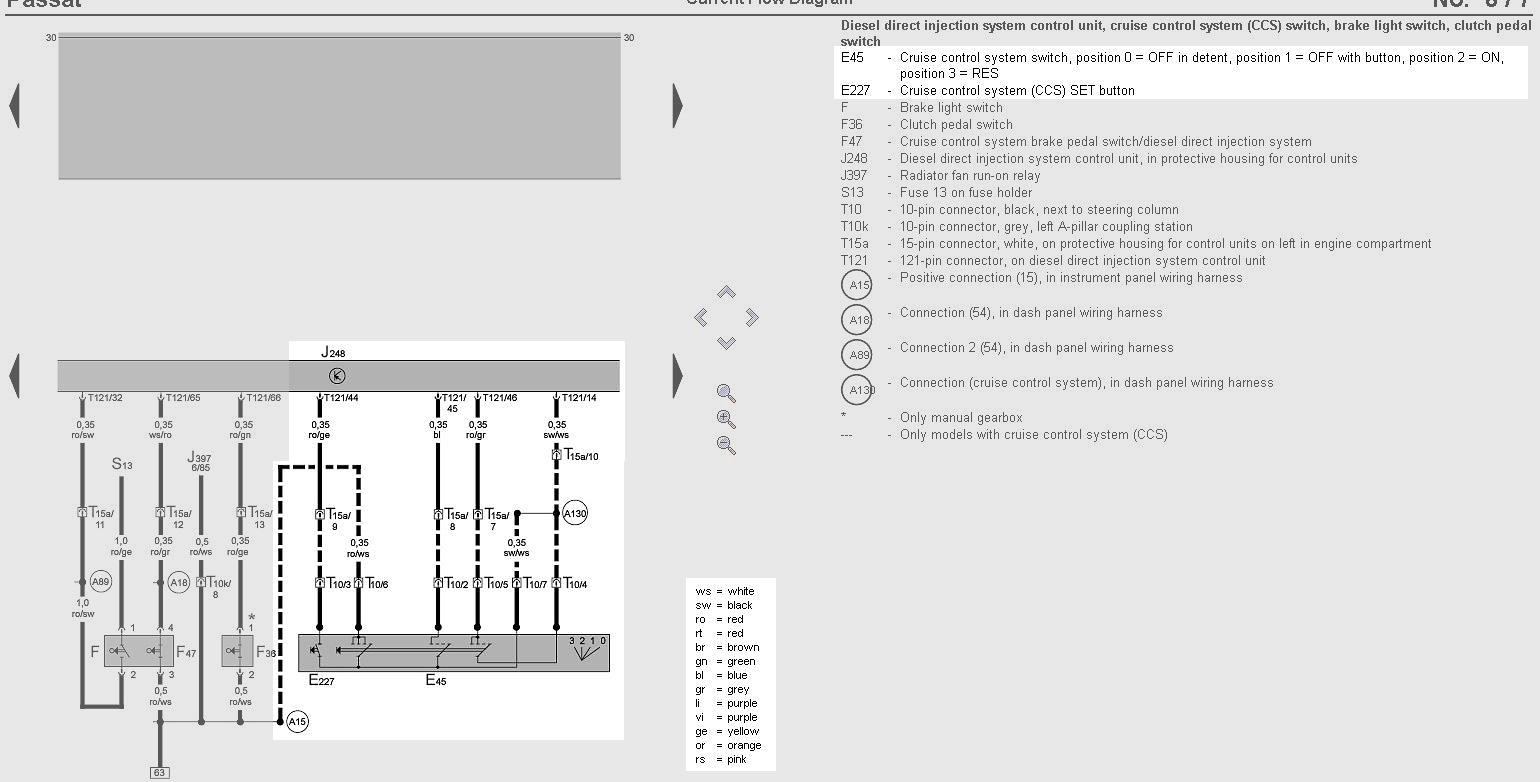
In my case, the cables from the loom was some strange colors so I have to manually check with multimeter the exact location. Two of them was tight together so that was pin 7&4.
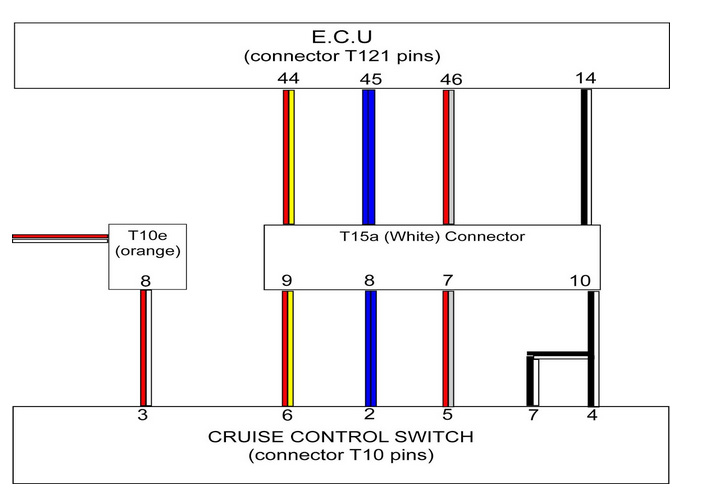
But anyway, here it is how it was in my case, you have the diagram above so you can do it easy:
T10[stalk side plug]
pin 7 -> black yellow -> pin 14 [T15A - white] -> black white
pin 4 -> black yellow -> pin 14 [T15A - white] -> black white
pin 3 -> red yellow -> pin 8 [T10E - orange] -> red white
pin 2 -> blue -> pin 8 [T15A - white] -> blue
pin 5 -> white-> pin 7 [T15A - white] -> red gray
pin 6 -> blue black -> pin 9 [T15A - white] -> red yellow
Now what?
- fit on place the cluster, ECU, and all plugs
- carefully put the new stalks (that with cruise control switches and the trip computer control).
- fit on place the cable spring unit , steering wheel and so on.. The steering wheel bolt must be tight about 60-80Nm!
- the airbag when is plugged to the cable, just “hit” it slightly with hand and will go on place
Now, when all is connected and you`re sure that all plugs are right connect the battery.
After that, you need to teach all your car keys (via VCDS, or other way) to that new cluster. For that “how to”, there are videos in youtube.
Next, activate the cruise control. For that again via VCDS:
- select 01. Engine
- Login 11
- enter code 11463 to activate cruise control.
When that is done, torn off the ignition key, then ON and when you slide the cruise control stalk to : ON , you`ll get the green symbol with arrow. That mean, all is good!
And finally:
Good luck!