Wednesday,24-May-2023
DMU50 Blum laser issues
EN
That is topic dedicated to annoying issue with one BLUM laser mounted on DMU50 machine with HEIDENHAIN CNC control.
In short, when the machine start to warm a bit, suddenly the laser stop working. In that state no measuring or in my case tool breakage detect. The device look as:
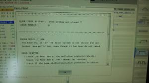
and the errors something as that:
Electric diagram:
There are :
- power supply
- control signal
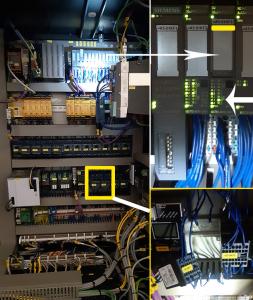
Here you see the electrical cabinet. Lower part are the both contactors that close the “enable” line. Upper is the unit that we are interested in.
Let`s look again the diagram
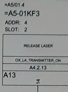
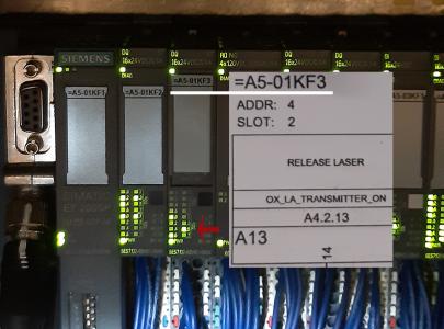
A5-01KF3 - is the code
14 - the bit related. Here it is 14. But if you lift the small blue label, there you see that under 14 the code outside is .5
OX_LA_TRANSMITTER_ON - the CNC variable that is used
Now, how to find the diagnostic? You need a code and go to some special NC section.
Let me be clear, if you write the code and mess with wrong section or data, that is YOUR problem and I`m not held responsible in any way!!
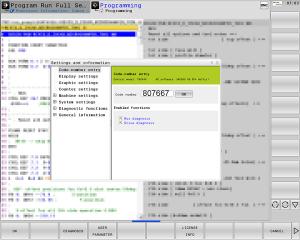
Program editing mode > pressing MOD > and enter:
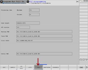
Then follow:
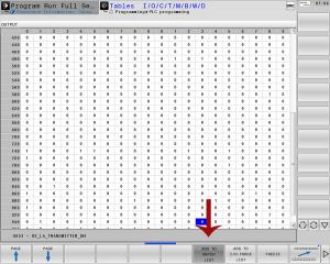
Must be chosen output signal list:
Wen found the right one, add it to fast access list:
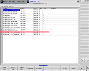
And we can call the list:
So far both the list variable and the physical unit led signal indicator showed that when requested laser to be ON , the result action is reach as it should be. So then what else can be? As additional information, I should point out that the BLUM unit have few led lights on it and you can see when it is ON and ready to operate. In my case it didn`t..
I decide to pay attention once again to the sheet:
There it said, that the Brown wire will be +24V and White the ground. Both will be present all the time machine is ON
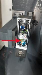
The open unit looked as that:
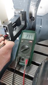
Fast test on the solder points showed:
That is way too low.
Next test was +24V and as ground the chassis:
At that moment the cable conduction test have to be made, and the cable should be identified:
The arrow point the marker, that can be seen also on the electrical drawing.
When the white and brown wires where taken out and tested for conductivity they seems fine.
Then the connector plug was taken out, cleaned with proper solution, the legs just bend a bit for better contact and all fit on place.
For now it work just fine, and seems the issue was caused by bad contact in my case.
Hope that will be helpful to you also! Take care..

