Saturday,21-November-2015
KENWOOD car player - control from steering wheel
EN
Hi there,
That DIY is dedicated to Kenwood KDC-6051U or how to use your steering wheel audio control buttons to take control over it.
Based on specs, the unit should accept commands on cable. That sound great, but there is bad news also - there isn`t any info about the protocol used(or at least I can`t find one). On the market there are products(of course from KENWOOD is the first option) that read your steering controls and put necessary codes to the unit. That cost about 60e for the box and 25e for cable in KENOOWD one, and little less for the other brands. That is quite a lot if the whole unit cost 170e.
From what I check on that “communication” cable constantly come +5V. There is no action if I tight it to pot and try different resistance. Well, obviously is not PIONEER/SONY way. My shot in the dark is that they use single wire protocol by pulling to GND that line in certain amount of time to generate start - 0 / 1 - end sequences, but to be sure I have to buy one ready and to check what is doing so it isn`t how will be for now.
So,my choice was to go other way - to clone the original RC-405 IR remote what come with the player and is suitable for other models too. For that purpose I`ve dig internet to find some info. And few of the websites are:
http://www.technoblogy.com/show?UVE
http://www.angelfire … nd/maza/kenwood.html
https://github.com/z3t0/Arduino-IRremote
NEC IR protocol - google
And it was quite helpful. My idea is based on ATMEL 85:

Just to mention that the resistors and ADC values are for my test. In your case you need to find out what real valueas are on your device.
Short story is: atmel read the resistors from steering and generate needed command. And the commands are:

If you need all of them, there is info in internet, or you can grab Arduino-IRremote library from the link above and just read your remote as I`ve done
the code is:
int tics, compare, tmp;

void setup(){

  pinMode(1,OUTPUT);

TCCR0A = (0<<COM0A1) | (0<<COM0A0) | (1<<COM0B1) | (1<<COM0B0) | (1<<WGM01) | (1<<WGM00);
TCCR0B = (0<<FOC0A) | (0<<FOC0B) | (1<<WGM02) | (0<<CS02) | (1<<CS01) | (0<<CS00);
OCR0A = 52;
OCR0B = 52;
tics = 0;
compare = 0;
tmp = 0;
}
void loop(){
  tmp = 0;
  tmp = analogRead(A2);
  delay(100);

if(tmp > 820 && tmp < 870){ sendCom(0xC837); }//SRC
if(tmp > 605 && tmp < 620){ sendCom(0x6897);  }// ATT20db
if(tmp > 360 && tmp < 390){ sendCom(0x28D7);  }// Vol ++
if(tmp > 230 && tmp < 250){ sendCom(0xA857);  }// Vol --
if(tmp > 160 && tmp < 190){ sendCom(0x30CF);  }// Prev Folder -
if(tmp > 110 && tmp < 130){ sendCom(0xB04F);  }// Next folder  +
if(tmp > 85 && tmp < 100){  sendCom(0x50AF);  }// Prev track -
if(tmp > 60 && tmp < 80){   sendCom(0xD02F);  }// Next track  +

}//--END LOOP--

void sendCom(long code){
  //---------------------- start transmition
  tmp = 0;
  carrier(31,345);
  carrier(52,172);
  long address = 0x9D62;
  //----------------------------------------
  for(int a=0; a<2; a++){
    for(int i = 15; i > -1; i--){
      if(1 << i & address){
           carrier(31,21);
           carrier(52,64);
      }else{
            carrier(31,21);
            carrier(52,21);
      }
    }
    address = code;
  }
    //--------------------- end transmit
   carrier(31,21);
   carrier(52,500);
}

void carrier(int duty,int comp){
       TCNT0 = 0;
       OCR0B = duty;
       compare = comp;
       tics = 0;
       do{
           if(TCNT0 == 52) tics +=1;
       }while(tics < compare+1);
}
That`s all, and if you have experience in atmel/AVR programming you`ll get it right away with no more explanation.
For all other like me who is more enthusiast than professional here is the story behind:

Ok, after you saw the image, blink twice to confirm and let`s continue ![]()
IR receiver has filter to get only standard 38kHz signal(well, that is most common one, and KENWOOD use that very one too), and that carrier over 38kHZ mean 38 000 times per second. That shout one “tic” every 26.316uS
So, if we have “0” state for 13.158uS and “+5V” for 13.158uS then that make one “square wave” with 50% duty cycle. Well, wave is not exactly right term here but forgive the rookie.
From what I found as info for IR remotes, that duty cycle must be about 25% to save power. Or 4 semi intervals “0” and 1 semi interval “1”. All that happen in 26.316uS. .
My set up for that atmel 85 is :16MHz @ 5V
16Mhz are - 16 000 000 cycles in one second or one “tic” every 0.0625microseconds
To “slow down” the things, there integrated functions named prescalers. That info you can find in the manual, and it looks like that:
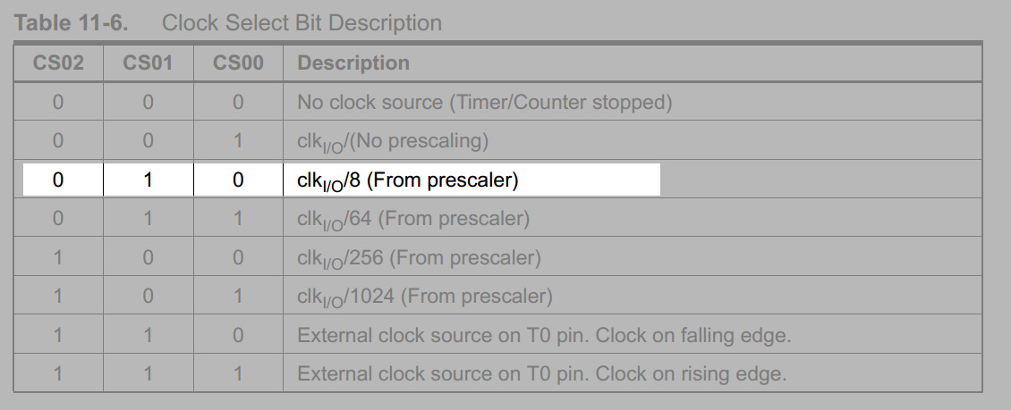
In my project I use prescaler of 8. Or the math will give - 16Mhz / 8 = 2Mghz or one “tic” every 500nS or 0.5uS. I need to generate 26.316uS pulses for my carrier so that must be:
26.316uS / 0.5uS = 52.632 counts
That`s great, but the CPU logic is not so happy about float points.. I that case i have to round:
52 counts * 0.5uS = 26.0 us -> 38 461HZ
53 counts * 0.5uS = 26.5 us -> 37 735HZ
Hm.. my choice went to 52 counts, and despite little over frequency the player accept it well.
Now, having 52 counts is time to set the hardware clock.
Idea: I wish to be inverted wave until counting the “empty part” of my wave cycle, then to have 1/4 pulse duty cycle what will be that +5V all that in 26uS for pulse.
How is done - by setting few registers for timer 0(8bit) which control digital pin 0 and 1(arduino use timer 1 for millis function).
- choosing Fast PWM mode, and top limit controlled by OCR0A( that is how long the pulse will be before reset),
OCR0B (how long will be the LOW pause before duty cycle)
Inverted mode is:

Set wave generation mode to depend on OCR0A for it top value
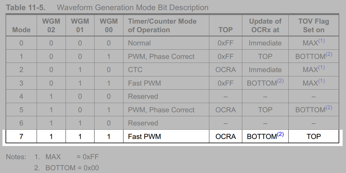
TCCR0A = (0<<COM0A1) | (0<<COM0A0) | (1<<COM0B1) | (1<<COM0B0) | (1<<WGM01) | (1<<WGM00);
TCCR0B = (0<<FOC0A) | (0<<FOC0B) | (1<<WGM02) | (0<<CS02) | (1<<CS01) | (0<<CS00);
To set OCR0A/B as top counters in invert mode (start LOW-HIGH, normal is HIGH-LOW)
Set prescaler:
TCCR0A = (0<<COM0A1) | (0<<COM0A0) | (1<<COM0B1)[/b] | (1<<COM0B0) | (1<<WGM01) | (1<<WGM00);
TCCR0B = (0<<FOC0A) | (0<<FOC0B) | (1<<WGM02)[/b] | (0<<CS02) | (1<<CS01) | (0<<CS00);
Clock counter register: TCNT0
And what`s going:
Counter TCNT0 start from 0, state is LOW , and every 0.5uS add one: 0-0.5(1)-1(2)-1.5(3)…
when TCNT0 = OCR0B , it become in state HIGH and continue until TCNT0 = OCR0A , or TCNT0 = 52, that is our 26uS pulse, and start again, and again and.. well you get the point.
What: OCR0A = 52; OCR0B = 52; - mean? - That mean it will keep it LOW(0) in every pulse.
Now to return on NEC protocol:
“0” - “described” as - 1.25ms - 560uS(HIGH)/560uS(LOW)
“1” - “described” as - 2.25ms - 560uS(HIGH)/1680uS(LOW)
To get what we need :
560uS / 26.316us ~21 “tics”
1680uS / 26.316us ~64 “tics”
9000uS - start signal are ~345 “tics”
4500uS - pause in the start sequence are ~172 “tics”
Now probably you get what:
carrier(31,345);
carrier(52,172);
in the code above mean. Now you`ll ask - is that`s all. Well, no. To the target IR code must be sent as: address + command.
The command for SOURCE is 9D C8. , but protocol require to be sent as:
9ms(HIGH) + 4.5ms (LOW) + address + address inverted + command + command inverted + ~560uS(HIGH) for end
Or again: 9ms(HIGH) + 4.5ms (LOW) + address + NOT(address)+command+NOT(command)+ ~560uS(HIGH) for end
And finally the full code-command for SOURCE is 9D62 C837. Also one important thing is that every bit is sent from the last to the first:
HEX: 9D62 C837 in binary is : 1001 1101 0110 0010 1100 1000 0011 0111 and will be sent as:
9ms->4.5ms-> 1>0>0>1>1>1>0>1>0>1>1>0>0>0>1>0>1>1>0>0>1>0>0>0>0>0>1>1>0>1>1>1>560us LOW and stay low
Well, that was all. Good luck, and hope it help to someone else
Add comment
Fill out the form below to add your own comments